Designing and Synthesizing a Better FFT
Edmund Lam and Barry Lyu
December 3rd, 2023
FFT Redesign and Optimization
The Fast Fourier Transform is an algorithm that converts time-domain signals into their frequency-domain representations. It has many different applications including audio processing, machine learning, etc.
In an earlier blog, we talked about the design of our ASIC FFT accelerator. Figure 1 from that blog post shows the architecture of it. This design used a Cooley-Tukey structure, in which each stage of the FFT is fully instantiated and FFT is composed recursively with smaller FFTs with half the sample points. However, this design is not especially space-efficient, because only one stage is used at a time, while all other stages are idle. In this blog post, we will talk about the optimizations we did to bring massive increases in both performance and area efficiency.
Earlier FFT Topology
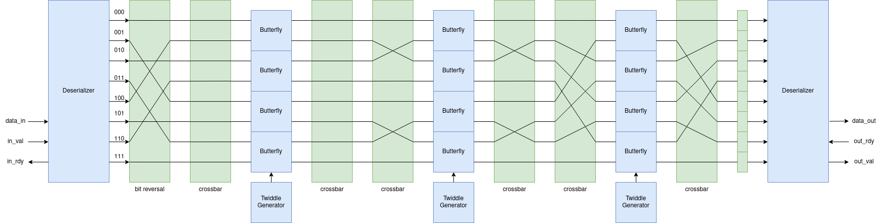
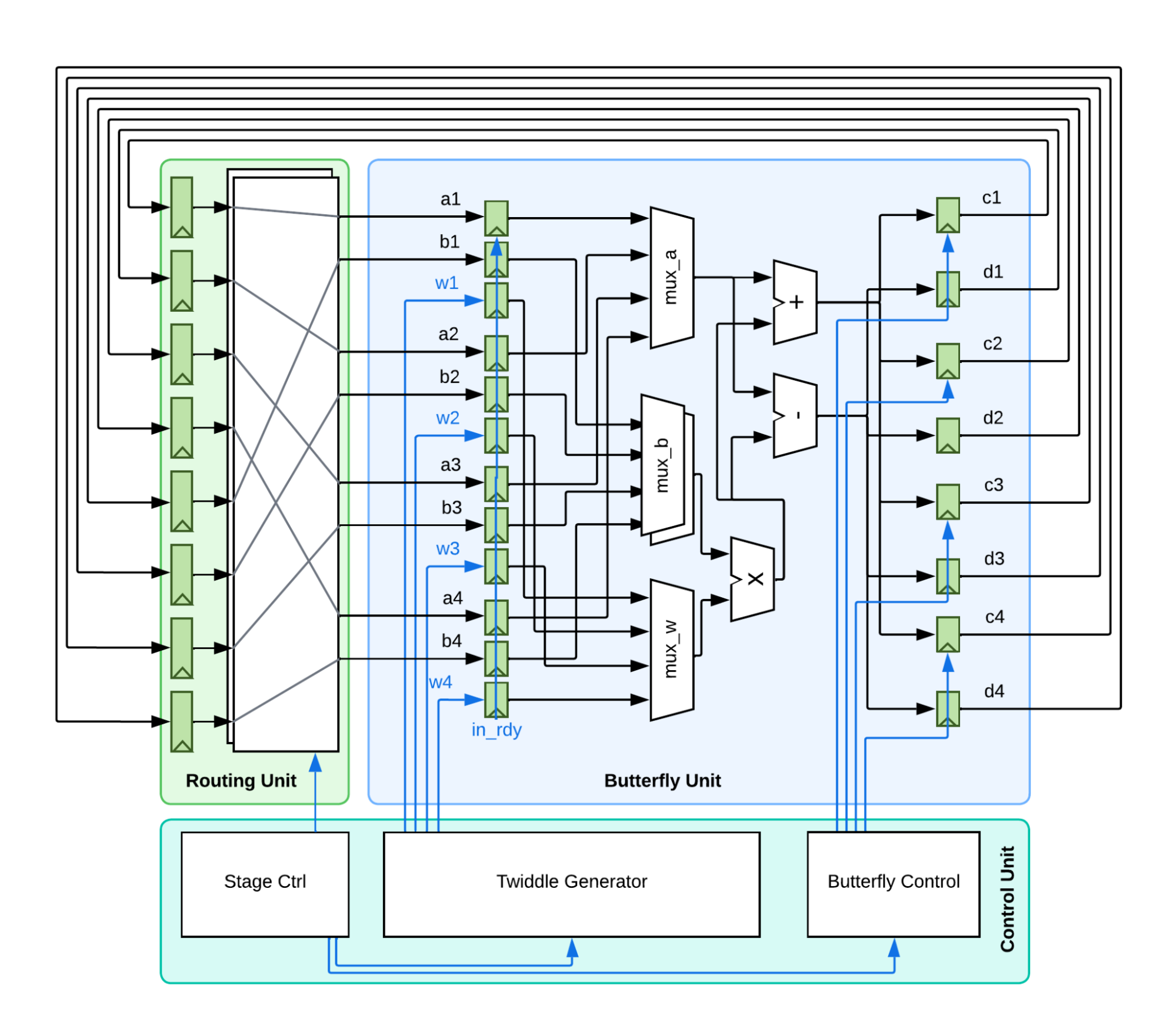
As in Figure 2 below, the newly optimized FFT adopts an iterative approach following the Pease FFT implementation. The Pease FFT is an adaptation of the Cooley-Tukey FFT, instead of instantiating all the stages with different inputs, it only instantiates one stage that is iteratively used. All the butterfly units are fixed in space, although their inputs are routed differently from stage to stage. This saves the amount of registers and multipliers needed drastically, especially for FFTs with large sample sizes (more stages). For an 8-point FFT, which has 3 stages, this means reducing the number of butterflies from 12 to 4, for a 32-point FFT, which has 5 stages, it reduces 80 butterflies to just 16. Furthermore, we implemented a multi-butterfly module, which allows several pairs of data points to share one butterfly. The butterfly would rotate between them and compute one by one. This means that we can adjust the number of butterfly modules freely to explore the optimal setup between area and performance.
Updated FFT Topology
Another optimization that is enabled by the reduction of butterfly modules is the use of single-cycle multipliers instead of iterative multipliers. Previous implementations of the butterfly modules used an iterative multiplier design to save space. However, iterative multipliers are extremely inefficient: multiplication between two 32-bit fixed-point numbers takes up to 32 cycles to finish. Since the new design has far fewer space constraints, we opted to use a single-cycle multiplier, which has higher cycle time and area, but far higher area efficiency and overall performance compared to the iterative counterparts.
Synthesis
The Manual Synthesis Flow
We synthesize our components using the caravel user project repository targeting sky130 PDK. Normally, this is a process that takes several steps:
- First, we run pytest in order to generate versions of our top-level fft module that has the right parameter values set for our design.
- Next, we copy our files to a clone of the caravel_user_project github repository, under the verilog/rtl directory.
- Then, we run sv2v to convert our SystemVerilog code into Verilog.
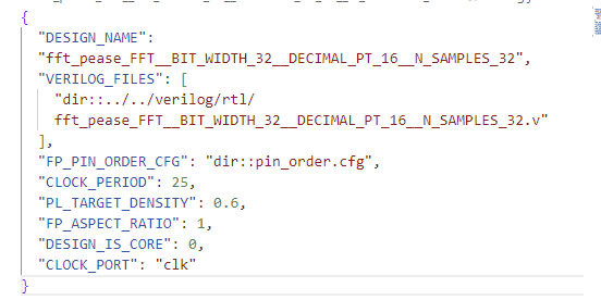
- Now that our Verilog is set up, we set up our OpenLANE files in a subdirectory of the openlane directory.
- To fill this out, we need a config.json file to tell OpenLANE what configuration we want for our designs, specifying things like the target clock period
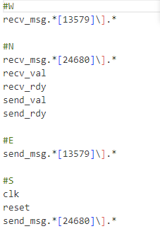
- Finally, we fill in pin_order.cfg, which tells OpenLANE which cardinal direction to place each of the ports in our design.
- With all our files set up, we can now push things through the flow using make design_name.
This is a process that not only takes many different steps, but is difficult to easily reproduce on other members' machines. The caravel_user_project repository is an entirely different repository from our workspace repository, so we would have to not only copy over many files to a different repository with a different structure, we also have to run pytest and find the right file out of potentially hundreds of generated files.
Most importantly, we often want to generate multiple macros for different parameter values, target densities, or clock periods. The steps above would have to be repeated for every single one of these combinations, which requires a lot of repetitive work that can be automated. This leads us to the custom automated caravel script we have developed for this exact purpose.
The Automated Synthesis Flow
In light of the issues described above, we have developed an automated synthesis flow for designs. Instead of all the steps needed above, now we only need to describe one config file per verilog module, with support for instantiating multiple designs with different parameter values using the same file. This new file is in the yaml format as it tends to be easier to look at, although our scripts support json as well.
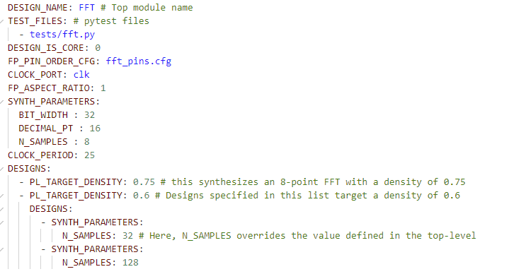
In this one file, we specify three different FFT designs - an 8-point, 32-point and 128-point FFT. These designs also have different target densities, and to shorten the configuration file as much as possible, we can nest designs and have parameter definitions propagate from the top-level designs to more specific ones. Other than this, we specify a single pin configuration file for our designs, and we are ready to synthesize.
To run synthesis, we type caravel src/fft/pease/fft.yml and our designs are automatically synthesized in parallel, and the results will be copied to a build directory once synthesis completes. This streamlines our work process significantly, allowing us to push through the flow quickly and often, facilitating design correctness and optimization.
The digital design process is characterized by many different incredibly powerful but difficult-to-master tools, and one of our biggest goals is to simplify this process and lower the learning curve so we as students are able to utilize these tools without needing years of experience in ASIC design and synthesis.