Electronic Design Automation: Creating Computers from Code
Angela Cui and Ethan Gabizon
November 19th, 2023
The process of producing an integrated circuit involves a meticulous process and knowledge in a variety of tasks: creating a high-level description, synthesizing a netlist of logic gates, performing physical design with placement and routing, and validating the design through simulation and verification at various points in this process. More than half a decade ago, all of these tasks would have to be manually carried out. Now, could you imagine performing these steps for today's billion transistor chips? Half a decade ago, this may seem like an impossible task. However, with the development of electronic design automation (EDA) tools, the modern electronic design industry is equipped with tools and methodologies that enhance design efficiency, reduce time and costs, and enable significantly more complex silicon systems. In this blog post, we will discuss how EDA tools impact C2S2's design process and the future of EDA tools in research trends.
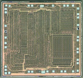
Launched 1975
~8500 transistors
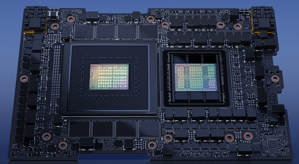
Launched 2022
>200 billion transistors
What exactly does EDA encompass? EDA is a category of software tools that help us design electronic systems, ranging from application-specific integrated circuits (ASICs) to printed circuit boards (PCBs). Most members on our team work with EDA tools in one way or another. The PCB design software used by the System Architecture team, the various analog circuit simulations performed by the Analog team, and the automated digital design flow used by the Digital team are all examples of EDA tools. The algorithms that perform static timing analysis and routing are examples as well. These tools allow C2S2 to execute fast paced designs. Members are able to perform simulations and validate blocks early in the year without a significant time bottleneck, thus enabling us to design complex hardware in a hierarchical manner.
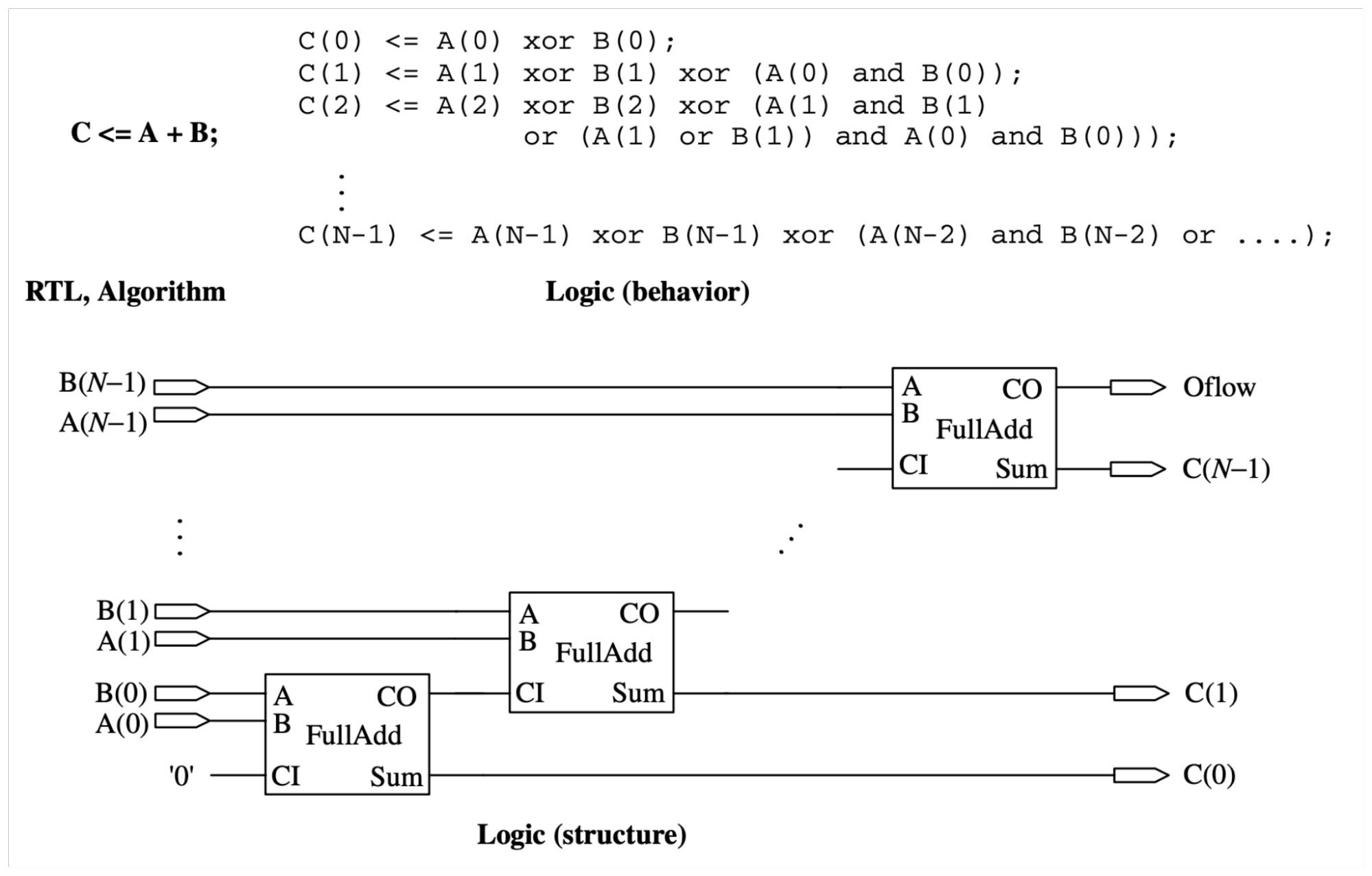
Further, with these tools in hand, we are able to abstract away hardware details and design on various abstraction levels. EDA tools are able to take various abstractions, such as in the figure below, and transform them into designs in file formats that we can then send to a PCB manufacturer or ASIC foundry. The power of abstraction greatly assists C2S2 in performing undergraduate semiconductor design by modeling complex systems, facilitating hierarchical design with well-defined modules, and simplifying the complexity of the design process.
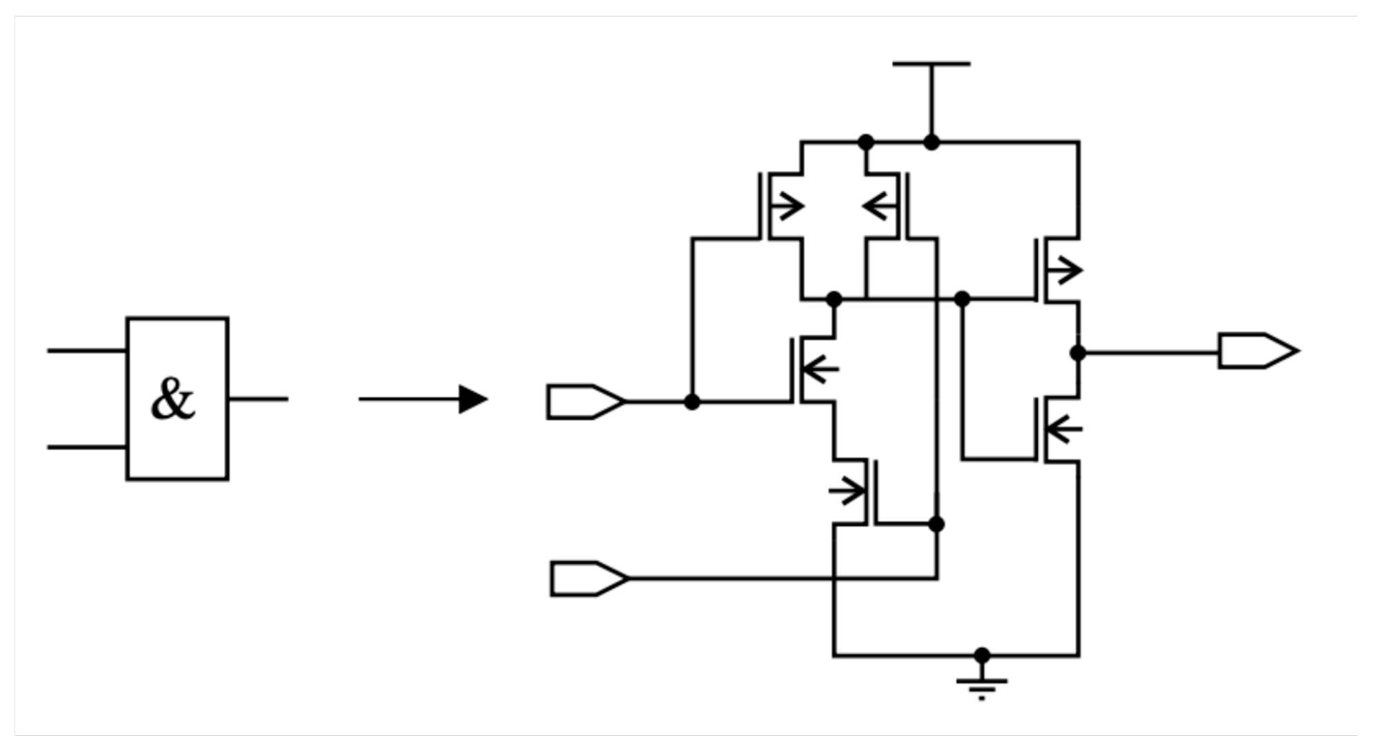
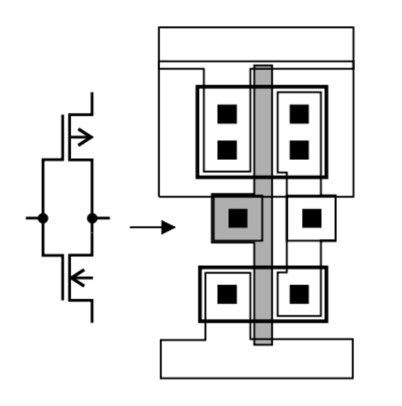
In addition to its ability to streamline the design process, EDA tools give us the actual hardware we are designing, in terms of transistor models. The development of EDA tools is tightly coupled with the development of process nodes. The properties of a specific semiconductor foundry are encoded in a set of files which make up a process design kit (PDK). C2S2 uses the open source SkyWater SKY130 PDK. The information stored in the PDK libraries, such as transistor size or timing characteristics, allow us to perform simulations and test our circuits to make sure they meet specifications before tapeout.
Apart from EDA tools that are used for hardware synthesis, as discussed above, research trends in the field have involved the development of languages and compilers that can generate hardware descriptions. In particular, high-level synthesis (HLS) toolchains transform a programming language functional description into low-level RTL code. One of the most well-known examples of an HLS toolchain is Vitis HLS, which compiles C++ programs to Verilog. While use of Vitis HLS is quite widespread in academia and industry, the last several years have also seen the emergence of more research projects that seek to answer the question of how we can leverage programming abstractions to make hardware design easier and more efficient. Google's open-source XLS toolchain is one such example, and is particularly exciting given its potential for use on C2S2.
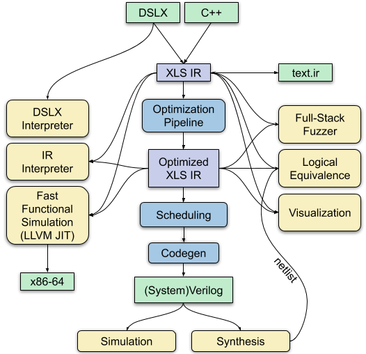
The goal of XLS is to provide software and hardware engineers with the tools they need to develop specialized hardware. XLS has two frontends, C++ and a novel language called DSLX, which was developed specifically for use in XLS. Given a program in C++ or DSLX, the XLS compiler builds an intermediate representation (IR). Many HLS toolchains use an intermediate representation that is based on a control-flow graph, which is a representation common in typical software compilers because it models the sequential execution of a program. However, this model is limited in its ability to represent hardware designs, in which many computations can occur in parallel. For this reason, the XLS compiler opts instead to use an IR that is closer to a 'sea of nodes' model, which has less of a rigid hierarchical structure than a control-flow graph.
Unoptimized Code
int x = 14;int y = 7 - x / 2;
return y * (28 / x + 2);
Optimized code after Constant Propagation
int x = 14;int y = 0;
return 0;
Optimized code after Constant Propagation and Dead Code Elimination
return 0;With the IR built, the XLS compiler performs a series of optimizations on it, many of which are typical compiler passes and some of which are specific to compilers that generate hardware descriptions. For example, the compiler performs dead code elimination, which removes unreachable nodes from the IR. Another common pass that the XLS compiler implements is constant folding, which has the potential to eliminate computational complexity from the IR. For example, if an arithmetic expression has only constants as inputs, the compiler is able to compute its value at compile time, rather than runtime (in this case, the "runtime" is the execution of the hardware). From here, the compiler performs many application-specific optimizations, which are targeted at generating the most efficient hardware descriptions possible. There are quite a lot of them, and they are detailed here.
A key part of the XLS toolchain is its ability to create schedules for the hardware it generates. When we design hardware, we often want to pipeline our designs. The XLS toolchain allows programmers to simply write a high-level description of a program, in which all notions of its underlying hardware or timing behavior are abstracted away. Then, the XLS compiler generates and pipelines the design using scheduling algorithms. The goal of this phase of the compiler is to determine the clock period of the design, and then find a schedule that minimizes resource usage while still meeting timing.
On C2S2, we have been experimenting with using XLS to generate some of our hardware blocks. For example, XLS has a parameterized floating point library implemented in DSLX, which can be used for our own modules that require floating point math. Using XLS for cases such as this would enable us to build more interesting and complex blocks without getting stuck in the low-level details of implementing a floating point library ourselves by hand. Additionally, using XLS would allow us to parameterize our designs over pipeline depth, so that we can have multiple blocks which compute the same operations but have different timing behavior, based on the specific use case of what we may want on the chip.