Testing and Validation of Printed Circuit Boards
Akshati Vaishnav and Kene Chukwuma
November 26th, 2023
Along with designing Printed Circuit Boards (PCBs), a major goal of the System Architecture subteam is to validate the functionality of the PCB after fabrication. This validation process can be split into five parts: visual inspection, component placement analysis, continuity and short testing, power supply check, and functional testing. In this blog post, we aim to explain this testing and validation process, while demonstrating our current work in this area.
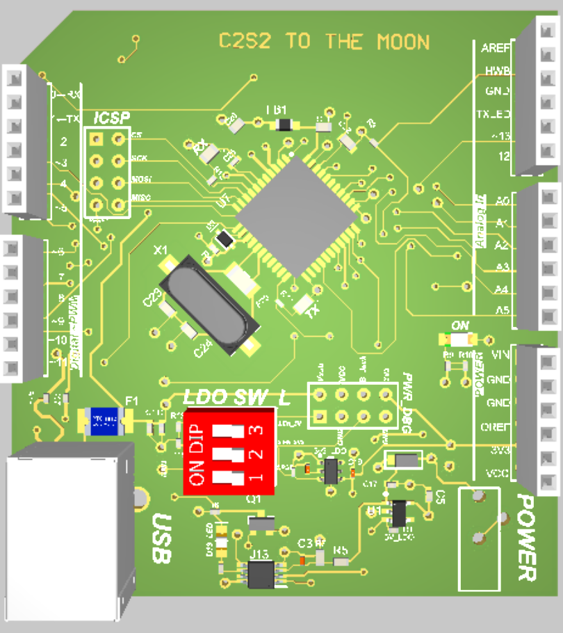
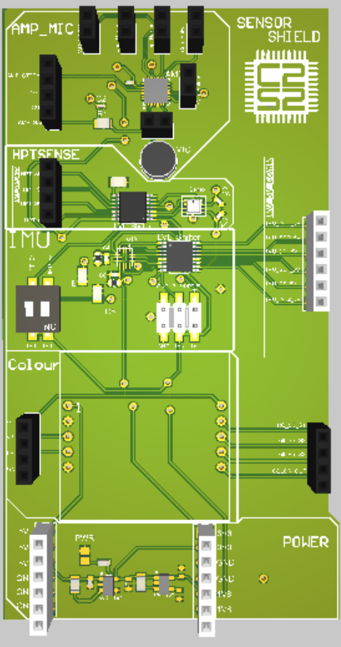
We first send our designs made using Altium for fabrication. Examples of some of the designs we have worked on are in the images below. The first image is of our Sensor Shield, which has various sensors for our use. The second image is of a PCB that supports the ATMEGA32U4-AUR microcontroller unit (MCU).
After we receive our fabricated PCBs, we begin with a visual inspection. This involves looking for any visible defects on the PCB such as solder bridges (unintended connections), missing components, incorrect component placements, or damaged traces. In order to do so successfully, it is important to use good lighting and sometimes even a magnifying glass.
Next is component placement analysis in which we ensure that all components are correctly placed according to the PCB design. We first ensure that all components are correctly placed according to the PCB design which we created using Altium. We then verify component orientation and polarity (for diodes, capacitors, and integrated circuits). Lastly, we double check that components are placed in their designated locations on the PCB.
Arguably, one of the most important steps in the verification process is continuity and short testing in which we use a multimeter to check for electrical continuity between various points on the board; we also ensure that there are no unintended shorts between traces or components. Unintended shorts are detrimental because they result in massive amounts of electrical current going through a circuit, which can harm parts used in the board. In using the multimeter, we first place one probe on ground and use the other probe to check continuity between all critical points on the PCB, ensuring that there is a complete electrical path where expected.
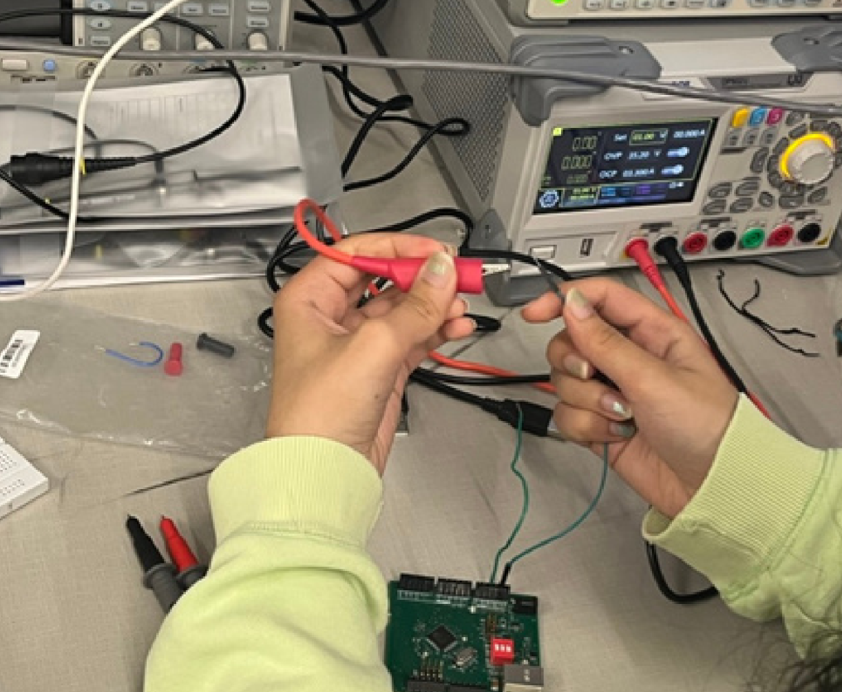
After the circuitry has been checked and has passed all tests, it is time to supply voltage to the board and test for functionality. When performing power supply checking, supply a range of voltages to the PCB and use a voltage meter or oscilloscope to measure voltage levels at critical points, such as power rails and voltage regulators. Lastly, we perform functional testing in which we connect the PCB to the intended system and check if it performs its intended functions.
The method of performing testing and validation can vary depending on which PCB we are testing. As an example, here were our steps in performing testing on the MCU PCB.
After fabricating the ATMEGA32U4 PCB, we performed visual inspection, component placement analysis, and continuity testing successfully based on the methodology described above. When it came to functional validation, we first attempted to write a simple LED blink program using the Microchip Studio IDE. However, we ran into issues getting both an on-board LED and external LED hooked up to the board to illuminate properly.
To troubleshoot, we researched how to configure the ATMEGA32 microcontroller to blink an LED using its native Atmel Studio IDE and assembly language programming. By stepping through the detailed instructions on register configuration and code execution in an article, we were able to understand exactly what needs to be set up in order to control the I/O pins and LEDs. Specifically, we learned how the DDR and PORT registers allow configuration of each microcontroller pin as either input or output. We also saw how the PORT register bits can be set high or low to manipulate external devices like LEDs connected to those pins.
Armed with this improved register-level grasp, we proceeded to test the LED blink code. By methodically walking through the logic in debugging mode within Atmel Studio, we could validate that the LDI, OUT, and other assembly instructions properly manipulated the PORTC pins in order to produce the LED state changes. Below is the code:
  #include <xc.h>
  #include <avr/io.h>

  int main( void ) {

      // Set PD5 as output
      DDRD |= ( 1 << DDD5 );

      while( 1 ) {
          // Turn LED on
          PORTD |= ( 1 << PORTD5 );
          // Delay
          for( int i = 0; i < 100000; i++ ) {
              asm( "nop" );
          }

          // Turn LED off
          PORTD &= ~( 1 << PORTD5 );
          // Delay
          for( int i = 0; i < 100000; i++ ) {
              asm( "nop" );
          }
      }
  }
After repeatedly reviewing the program execution to strengthen our comprehension, we successfully uploaded the finalized code to the physical ATMEGA32 chip on our PCB. Both onboard and external LEDs now properly turned on and off in the expected blinking pattern, proving full functionality! This experience demonstrated how clearly understanding internal microcontroller behavior through register manipulation is essential to be able to control and validate external device operations.
To methodically validate the performance of our designed PCBs, we also create testing tables to track measurement equipment used, specific parameters verified, and pass/fail outcomes for each component. Below are the tables we utilized during the validation process for our MCU PCB:
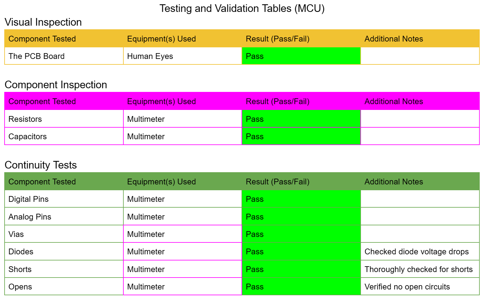
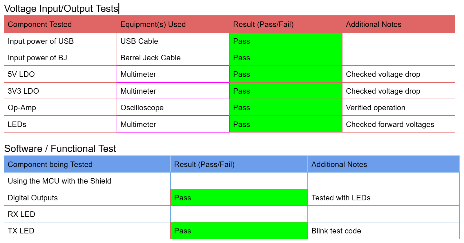
By using such rigorous testing tables during PCB validation, we can be confident that any potential fabrication issues are caught prior to system integration.