Progress Report - 4/23/2023
Christopher Schiff and Johnny Martinez
April 23rd, 2023
Hi, my name is Johnny Martinez, and I am one of the new members of C2S2's digital subteam! I am an ECE major, but I am also very interested in computer science and statistics. Getting onto C2S2 has been a goal of mine since freshman spring, and I am happy to say my time on the team so far has been both rewarding and exciting! My current project involves creating a router for our current FFT system architecture.
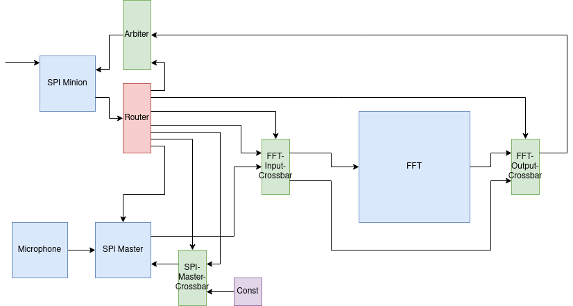
FFT System Architecture Block Diagram
The original implementation of the router designated the first log2(# of outputs) MSBs of the input message to determine which output port received a high valid bit. It then sent the message to all of the output ports, as well as the correct valid bits. I used a parametric mux to select the proper ready bit from one of the receiving ports and a parametric demux, that I also made, to select and assign a high valid bit to the correct output port. At first, I went about testing my router using a harness that wrapped all of the outputs that were unpacked arrays into three binary numbers ( for the valid bits, ready bits, and output message bits). For example, say we have two output ports connected to the router. To test that the correct valid bits were being output, I would take all the output valid signals and merge them into one number via the harness. So, I would expect something like 10 or 01 depending on which port was selected. However, I have recently learned of a better way of testing blocks with unpacked arrays in PyMTL that does not need a wrapper thanks to Professor Batten and it has made testing substantially easier! Let's take a closer look at one of the test cases I wrote for the most recent implementation of the router that does not clip off any bits:
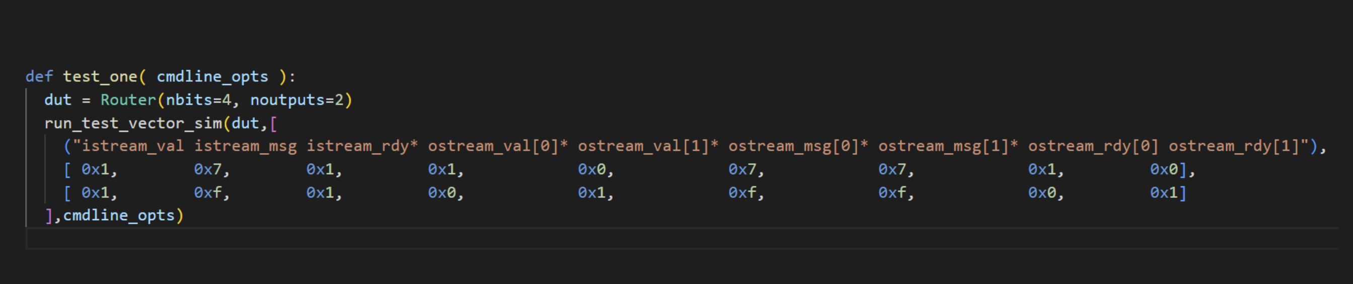
A Simple FFT Test Case
Here, I am instantiating a router that takes in a four bit message and has two output ports. We test the router with two different input messages, 0111 and 1111. The first input message has 0 as the select for the demux and the mux because it is the MSB of the message. Thus, the ready bit from the first output port (ostream_rdy[0]) will be used for the istream_rdy value (i.e the ready signal for the router block). The selected output port will also receive a high valid bit (ostream_val[0]). When 1111 is the input message, the second port is selected so ostream_rdy[1] and ostream_val[1] are used or assigned a high bit. Also, notice the output message is the same as the input message because no bits are removed from the message.
Aside from no longer removing bits, the current implementation of the router utilizes a queue to make the block more versatile. I am still working on adding this component to the router, but I am currently exploring the functionality of the queue block with the test bench I created. Before I add the piece to the router, I want to make sure I fully understand how it works.
Hello! I'm Christopher and I am also an ECE major. As a member of the digital subteam, my work has been focused on exploring using open-source high level synthesis (HLS) tools as part of the team's design flow. To clarify, HLS tools aim to enable digital circuit design using high-level programming languages like C++ as opposed to hardware description languages (HDLs) like Verilog. By raising the level of abstraction, HLS can give many advantages over "manual" design such as greatly improved productivity, more efficient hardware-software codesign, and rapid design exploration. While HLS tools have been around for quite some time now, as with much of the rest of the ASIC flow the most common EDA tools (e.g. Mentor Catapult, Vivado/Vitis HLS) are commercial and closed-source.
Specifically, I have been exploring design using XLS, a new, fully open source HLS toolchain started by Google engineers. While XLS is a large project with many different components, the novel frontend, DSLX, is probably the most interesting. DSLX is a domain-specific language (DSL) designed specifically as a dataflow-focused functional language for digital circuit design. Dataflow languages are a subclass of programming languages specifically designed for parallel processing. They model computations as a set of tasks, where data flows between them. This is perfect for hardware design because it allows you to express complex parallelism and concurrency naturally While very similar to Rust at first glance, DSLX has a fair number of differences that make it more suited to hardware design, and are focused around enhancing parallelism and simplifying the translation from a high-level language down to an HDL.
One of the more prominent of these features is DSLX's immutability. When working with an immutable system, a variable's value, once assigned, remains constant and cannot be altered. While this concept may initially seem limiting, with respect to digital hardware design (and dataflow oriented hardware in particular) it actually provides many different advantages to both the designer and the compiler. On the designer's end, the need to set a new variable whenever the value needs to be changed clarifies the dataflow and makes avoiding issues like race conditions much easier. For the compiler, immutability ensures the high-level code can be easily translated into the intermediate representation (IR) language where optimization passes and the final HDL code generation is performed. As an example, here is the top level function for the bit reversal module I designed as part of a DSLX-only alternative FFT module:
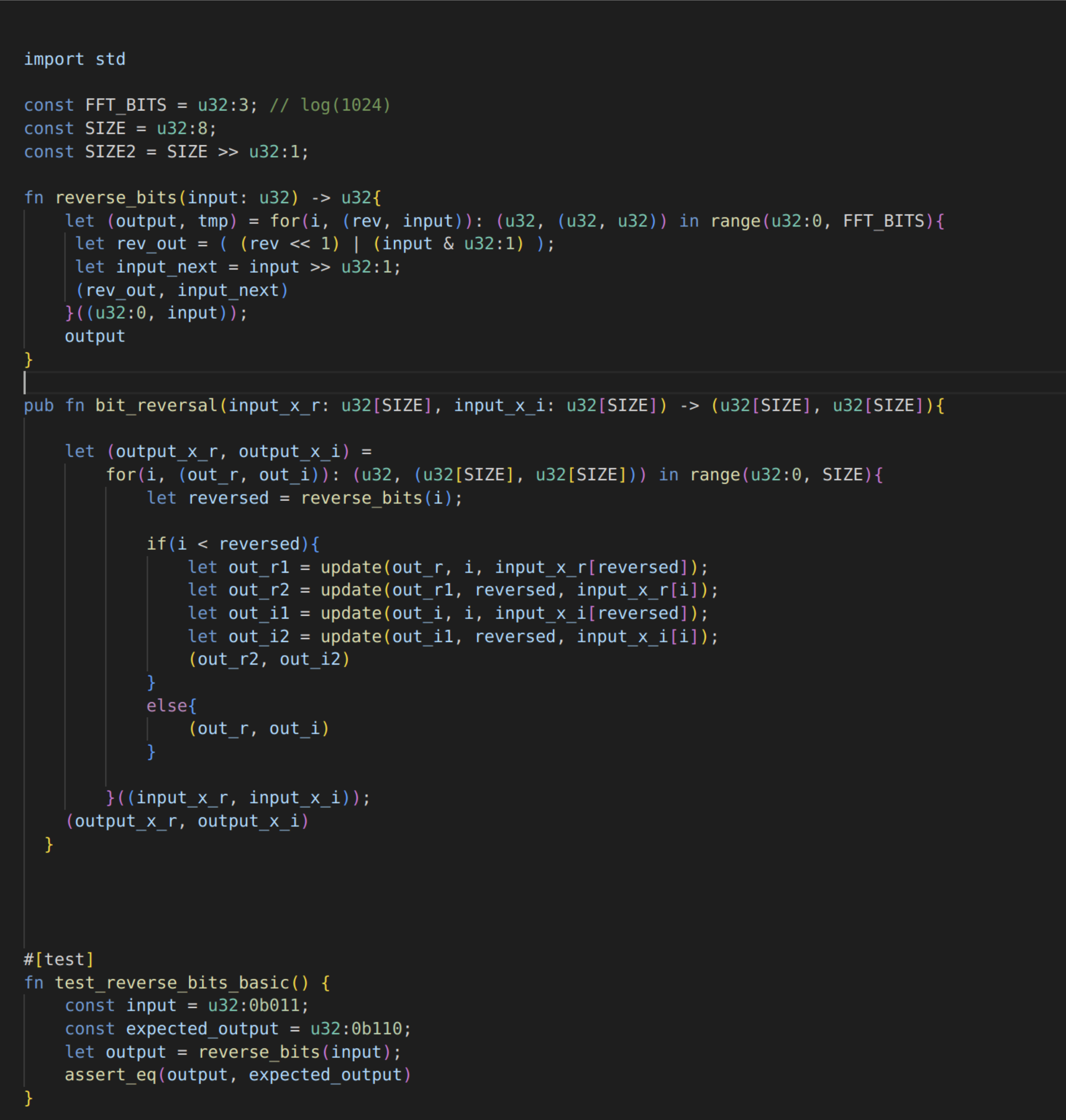
HLS Example - Bit Reversal Module
This module/function rearranges the inputs according to the bit reversal algorithm. You can see that in the inner loop, a new array is created (via the "update" function) every time the values need to be updated. While this is a very simple example, in a much larger function this necessity would make it much easier for the designer to track and organize how the data arrays change.